
from my practise with PC-hardware.
Hier geht's zur
deutschsprachigen Version
Go here to the
German version
Because I don't advertise free for any company on this page any names of companies or products aren't called here! If you want to know something about this please send me an email.
00. Index01. RAID-0 with two IDE-harddisks
02. RAID-0 with three or four IDE-harddisks
03. Use a harddisk from a laptop in a PC
04. Trouble with the RS232 pins
05. "Complete" shutdown of an ATX PC = disconnect it from the electric network
06. Protection against overvoltages (device protection)
1. RAID-0 with two IDE-harddisks
The harddisk drives (short: harddisk, abbr.: HDD) are the "bottlenecks" in every computer except servers
with 10 or 20 HDDs on a RAID-controller. The most PCs contain IDE-HDDs because they are cheaper than SCSI-HDDs with an approximate same
capacity. The slowness of the machinery in all modern HDDs forces down their performance. RAID-0¹ offers
one of the possible ways out. If the machinery of one HDD is working momentarily the next datas are demanded from the next HDD. Nearly all
PCI-mainboards have two IDE-controllers those are connected to the PCI-bus. Two IDE-devices, always one as master and one as slave, can be
connected with each controller. Unfortunately the two devices connected with one controller slow down each other because only one
device is accessible at one time. Both devices work only with the maximum transfer mode of the slower device especially on older mainboards.
¹RAID: "Redundant Array of Inexpensive Disks" or "Redundant Array of Independent
Disks"
¹Level 0 = "Striping": The datas are shared approximatively parallel onto the HDDs. Any data
protection exists!
To use two HDDs which are connected with the onboard-IDE-controllers with RAID-0 the following conditions are
required:
One HDD is connected as master with the first onboard-IDE-controller, the other one is connected as master with the second
onboard-IDE-controller. ATAPI-devices (CD-ROM drives, CD-writer, DVD-ROM drives, etc.) must be connected as slaves. Attention please! Older
ATAPI-devices can slow down with their slow maximum transfer mode the HDDs. The operating system must support software-RAID-0. The two
HDD-partitions which should be used with RAID-0 should have the same size.
Hardware and operating system must support busmaster-DMA or Ultra-DMA. RAID-0 could be used with the PIO-modes on principle but all datas
pass through the CPU in this case. Because the CPU is loaded extremely in this case the performance isn't increase.
Almost all onboard-IDE-controllers on socket-7-mainboards support Busmaster-DMA (Multiword-DMA 2), controllers on socket-7-mainboards of the
last generation support Ultra-DMA/33 partly. Controllers on mainboards with newer sockets than the socket-7 support Ultra-DMA/33,
Ultra-DMA/66 or Ultra-DMA/100. Controllers on brandnew mainboards support Ultra-DMA/133 sometimes as well. The situation is the following
for the HDDs:
| capacity | transfer mode | abbreviations | transfer rate | slower transfer modes |
| ~0,5 GB | Multiword-DMA 1 | MDMA1; Mode 3 | ~11 MB/s | MDMA0 |
| ~1 GB | Multiword-DMA 2 | MDMA2; Mode 4 | ~16 MB/s | MDMA0, MDMA1 |
| ~4 GB | Ultra-DMA/33 | UDMA2 | ~33 MB/s | MDMA0, ..., MDMA2, UDMA0, UDMA1 |
| ~8 GB | Ultra-DMA/66 | UDMA4 | ~66 MB/s | MDMA0, ..., MDMA2, UDMA0, ..., UDMA3 |
| ~20 GB | Ultra-DMA/100 | UDMA5 | ~100 MB/s | MDMA0, ..., MDMA2, UDMA0, ..., UDMA4 |
| ~60 GB | Ultra-DMA/133 | UDMA6 | ~133 MB/s | MDMA0, ..., MDMA2, UDMA0, ..., UDMA5 |
A few HDDs support the ancient singleword-DMA-modes (Sword0, Sword1, Sword2) too. That's mentioned here only for the
completeness.
The transfer rate is the one between the HDD-cache and the IDE-controller. The mechanical part of the HDD is considerably slower every time.
The real transfer mode corresponds to the maximum transfer mode of the slower participant (IDE-controller or HDD). Attention please! If both
participants support Ultra-DMA/66 or higher they must be connected with a special Ultra-DMA/66-cable (80-wire, 40-pin).
If a normal IDE-cable is used (40-wire, 40-pin) Ultra-DMA/33 is the maximum possible transfer mode! Only devices that
support Ultra-DMA/66 or higher may be connected with an Ultra-DMA/66-cable. All modern operating systems support Ultra-DMA/133 and all slower
transfer modes but the use of busmaster-/Ultra-DMA must be extra activated on many operating systems.
The HDDs shoudn't have very different transfer modes and access times. Otherwise RAID-0 would work with one very slow HDD slower than the
fast HDD alone.
2. RAID-0 with three or four IDE-harddisks
In this case all is valid what's said to RAID-0 with two HDDs. An offboard-Ultra-DMA-controller and the HDDs of
course are required. An offboard-Ultra-DMA-controller is a PCI-card with two IDE-controllers.
Advantages: On principle 8 IDE-devices can be connected. The actual offboard-Ultra-DMA-controllers support Ultra-DMA/133 and HDDs up to a
capacity of 100 GB and more. Through that HDDs with a large capacity can be used with their maximum performance with older mainboards
together. The HDD capacity limit of the mainboard-BIOS doesn't affect the HDDs connected with the offboard-Ultra-DMA-controller
because these controllers have their own BIOS. Controller and HDDs are considerably cheaper than an SCSI solution.
Disadvantages: The offboard-Ultra-DMA-controller requires one free PCI-slot, one free interrupt (IRQ) and some free address-ranges. The
address-ranges don't cause any problems normally but the available IRQ's are limited strictly into a PC. In practice only 6
IDE-devices can be connected. ATAPI-devices which are connected with an offboard-Ultra-DMA-controller very often cause problems with many
operating systems. Therefore only the two HDDs with the highest performance are connected as masters with the offboard-Ultra-DMA-controller.
The ATAPI-devices and the slower HDDs are connected with the two onboard-IDE-controllers. Not all offboard-Ultra-DMA-controllers are
supported by all operating systems. Moreover the controller costs money (ca. 60,- €).
3. Use a harddisk from a laptop in a PC
 600 dpi JPEG |
The laptop was equipped with a new HDD and the old one is buried under layers of dust anywhere. That mustn't be! This HDD can be mounted into a 5¼" slot with a few additional things. Unfortunately many 2½"-IDE-HDDs don't accept any second IDE- or ATAPI-device on the same IDE-controller so that these HDDs must be separately used as master on one IDE-controller but one or two HDDs and one CD-ROM drive should be enough in the second PC ;-) |
The HDD and the things listed below are reqired for the installation:
- 1 pcs. Caddy to use a 3½" drive in a 5¼" slot
- 1 pcs. Ribbon or cable for the HDD-to-ground connection (minimum diameter 1,5 mm², length ca. 100 mm) with ring terminals, inner hole diameter of the terminals 3 mm or 4 mm if necessary (only needed, if a plastic caddy is used)
- 1 pcs. Aluminium tube with a square profile, 10×10 mm outer diameter, wall thickness 1,0 mm
- 4 pcs. Screw with cylindrical head M3×10 (or M3×5 - M3×20; what's just available)
- 4 pcs. Screw with cylindrical head M3×15 (or M3×16)
- 4 pcs. Screw with cylindrical head M3×20
- 4 pcs. Nut M3
- 8 pcs. Nut M4 (as spacers)
- 16 pcs. Plain washer ISO 7093 M3 (these are the ones with the large outer diameter, here ca. 9 mm!)
- 1 pcs. adapter 2½"-IDE to 3½"-IDE (adequate for SCSI)
The following tools are required:
- Screw-driver (to screw the screws M3)
- Spanner (= wrench) with 5,5 mm width across flats (It's impossible to arrest a nut M3 with 6,0 mm width across flats!)
- Stork bill tongs (to arrest difficult accessible nuts)
- Drilling machine with HSS twist drill 4,5 mm
- rat-tail file (to remove the chips from the drill holes)
- Metal saw (to cut the aluminium tube)
- small file with minimum one flat side (to remove the chips from the cutted aluminium tube segments)
- Vice or other tool (to fix the aluminium tube)
- Steel tape measure or ruler
- thin felt-tip (It's nearly impossible to perceive marks on aluminium that are marked with a pencil or a scribing iron.)
If it's possible a metal caddy should be used because the threads for the fortification screws don't get broken too fast.
A ribbon to connect the HDD with ground isn't required because the metal caddy will connect the HDD with ground. Unfortunately it isn't easy to
get a metal caddy. Plastic caddies have normally a front panel with a break-through for a 3½"-floppy-disk drive. This isn't
required here. The front panel is sawed off ca. 8 mm behind the front panel. Because the ground panel of the caddy is cutted a little too a
closed front panel can be placed before the slot.
The following steps are shown in a drawing.
To segments are cutted in each case with a length of 120±5 mm from the aluminium tube. The chips are removed from the cutted aluminium tube segments, inside too! The places are marked for the drill holes. The lateral tread holes of the HDD are used. The drill holes are marked for the fixation on the caddy. The four outer lateral brackets of the caddy are used for fixation. All holes should be drilled nearly in the middle of the transverse line of the aluminium tube segments. The holes are drilled and the chips are removed. Only the loose chips inside the tube can be removed in some cases. The chips sticked inside the tube are leaved behind as a "residual risk". They can be removed with a special tool too. Do this if you have such a special tool! The aluminium tube segments are beated and blowed out. At first the HDD is screwed together with the tube segments. Two nuts M4 are used as spacers in each case. One plain washer ISO 7093 M3 is placed under each screw head and each nut. Through that the aluminium tube segments aren't squashed. The plain washers can't be placed under the nuts M4 because there isn't enough place between them and the HDD or the tube segment and in this case it isn't required too. The HDD that's screwed together with the tube segments is placed in the caddy and they are screwed together. It's difficult to arrest two of the nuts and plain washers M3. It's nearly impossible with the spanner. Therefore the stork bill tongs must be used. Now the adapter is plugged onto the HDD. ATTENTION PLEASE! 2½"-IDE-HDDs have a 50-pin connector. The following image illustrates the pin assignment:
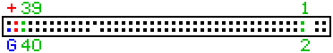 |
Pin 1 is assigned to hole 1 on the adapter. If this mark has been unfortunately lost the side of the adapter can be find out where the power connector is placed in any case. The two first holes on these side of the adapter belong to the pins G = ground (0 V) and + (+5 V) on the HDD. Now the complete unit is placed in the PC like a normal 5¼" drive and it's connected with the power supply and the IDE-controller. The HDD can be used just like a normal 3½"-IDE-HDD.
back to the index4. Trouble with the RS232 pins
PCI-mainboards are normally equipped with two RS-232-ports ("serial ports") which are accessible via 10-pin male connectors. Unfortunately any standard pin assignment was implemented so that two pin assignments exists (minimum?). Because the 9- and 25-pin SUB-D-connectors that are used to connect external devices with the computer have a standard pin assignment two internal pin assignments cogently exists (minimum?) at the inner side of these connectors. If the mainboard and thats additional components stay together more or less any problem will occur. But a big trouble can occur if a PC is build with components out of the stuff box. Some people will panic already if their serial mouse and modem don't work in this case although they have worked fine previously and the software don't have any obvious errors. The dilemma discloses himself only after a look into some wired SUB-D-connectors. The following table shows the two different internal pin assignments that I've found till now:
| assignment 1 | assignment 2 | |||
|---|---|---|---|---|
| male connector | 9-pin SUB-D | 25-pin SUB-D | 9-pin SUB-D | 25-pin SUB-D |
| 1 | 1 | 8 | 1 | 8 |
| 2 | 2 | 3 | 6 | 6 |
| 3 | 3 | 2 | 2 | 3 |
| 4 | 4 | 20 | 7 | 4 |
| 5 | 5 | 7 | 3 | 2 |
| 6 | 6 | 6 | 8 | 5 |
| 7 | 7 | 4 | 4 | 20 |
| 8 | 8 | 5 | 9 | 22 |
| 9 | 9 | 22 | 5 | 7 |
| 10 | NC | NC | NC | NC |
NC = not connected
If the used connector has the wrong internal pin assignment and any connector with the correct internal pin assignment is
available it's possible only to remove and connect again the wires with the internal pins of the SUB-D-connector in the right way with a
soldering iron. The 10-pin female connector for the connection with the mainboard is connected with the IDC method of termination. Therefore
it isn't accessible for changes.
As well the RS232-ports are on a controller-card (usually by ISA- and VLB-mainboards, very rarely by PCI-mainboards too) at least one of
these ports is accessible via a 10-pin male connector whereby the (minimum?) two assignments exist that are described above.
5. "Complete" shutdown of an ATX PC = disconnect it from the electric network
The ATX standard has introduced many advantages but it has introduced one aggravating disadvantage too. If an ATX computer
is shut down or "turned off" with the momentary switch button on the front panel the computer is not disconnected from the
electric network! The power supply is supplied with AC power after that to supply the circuit +5V STB (= standby) with power.
Ecological alert!
This is waste of energy!
This is dangerous too because hazardous overvoltages can attain to the computer at any time!
This problem exits with the older AT power supplies as long as the computer is switched on. The switch disconnects these computers all-polo
from the electric network.
To disconnect an ATX computer all-polo from the electric network a switchable multiple socket is required. This switchable multiple socket
must be accessible easily for the user. If any other overvoltage protection doesn't exist a switchable multiple socket with an integrated
overvoltage protection is reqired. The computer and all peripheral components (monitor, printer, scanner, MIDI-keyboard, active speakers, ...) are switched via this multiple socket because some
newer peripheral components haven't a switch that disconnets them from the electric network. Some external modems have some non-volatile
memory. These modems can receive telephone calls and faxes as well if the computer is turned off and disconnected from the electric network.
If this function should be used these modems mustn't be switched via the multiple socket because they require a permanent supply of electric
power.
The procedure described above is recommended as well for all other electronic devices that are switch into a standby mode only after
they are "turned off" (TV, radio, CD-player, ...). Only those devices are connected permanent with the electric network that make
programmed records (video recorder, ...) or must be able to receive something at any time (answering machine, fax machine, telephones that
require a power supply, ...).
6. Protection against overvoltages (device protection)
Three essential kinds of overvoltages exist:
1. Overvoltages with large power (W) and a very fast increase of voltage (du/dt), caused e.g. by a lightning stroke. Any efficient device
protection isn't available against these overvoltages. If any lightning rod doesn't exist that was it!
2. Overvoltages with large power but only a moderate increase of voltage, caused e.g. by the switching of high inductive loads. Overvaltages
of this 2nd kind are normally discharged with gas discharge arresters, in the case of a load that's supplied with DC voltage with recovery
diodes (fast switching diodes) too. The switching of high inductive loads is rather unusual at home. Modern house wirings are
equipped with gas discharge arresters placed in the house connection box. So overvoltages from the external electric notwork are
discharged. Be careful if e.g.a handicraft enterprise resides in the house where you living!
3. Overvoltages with low power but a very fast increase of voltage (also called "line transients"), caused e.g. by phase
controllable devices (dimmers, drilling machines with "electronic"), frequency changers and switching power supplies (the power
supplies in our computers are switching power supplies too!). Overvoltages of this 3rd kind have strongly increased in the last years and are
very usual at home too. If a usual 16 A fuse switches off a 230 V AC line this can cause such an overvoltage with a peak voltage up to 1 kV.
The electrostatic discharges (ESD) belong to this kind of overvoltages too. Who didn't get an electric shock sometimes when he/she
touched a larger metal object after a walk over a synthetic floor? It's spoken often about the ESD protection in this case. Overvoltages of
this 3rd kind are discharged with varistors, by low voltage applications with supressor diodes (extrem fast switching diodes) too. The
protection component must be always placed electrical as near as possible by the device that must be protected because the very fast increase
of voltage causes already transit time effects on the lines. Therefore the best place for the protection component is electrical between the
power supply and the device that must be protected!
Unfortunately consumer ware doesn't contain a varistor in the most cases :-(
The semiconductors in the electrical devices aren't thermally destroyed trough overvoltages of this 3rd kind because these overvoltages have
only low power. The very fast increase of voltage du/dt destroys the semiconductors because they tolerate only a maximum du/dt value in each
case.
To protect the computer (and other electrical devices connected with the electrical network) against overvoltages of this 3rd kind
they are all connected to a switchable multiple socket with an integrated overvoltage protection. This switchable multiple socket must contain a varistor and not only a slow gas discharge arrester.
Unfortunately the solution with the multiple socket has one disadvantage for permanent running computers. "Why is this multiple socket
still switched on?" Click :-(
Adapters with an integrated varistor based overvoltage protection are meanwhile available on the market. These adapters are useful for devices in 24/7-operation.
Special adapters with an integrated varistor based overvoltage protection are available for computers. These adapters protect against overvoltages of the 3rd kind from electrical network, LAN (ethernet, RJ45-cable), modem/ISDN/DSL (RJ11-cable) and the antenna cable (to TV-card).
Here was repeatedly talked about the varistor: "How does it work?"
|
|
A varistor (metal oxyde varistor, abbr.: MOV) is a nonlinear, voltage depending resistor. Formerly it was called "VDR" (voltage depending resistor). Nowadays "varistor" or "MOV" is more usual. It is used below its breakdown voltage with only very few exceptions. In case it's normally used it's only a resistor with a very high resistance (R >= 1,0 GΩ). If the voltage on the varistor increases only a little bit over this breakdown voltage the resistance of the varistor will rapidly decrease (standard types <= 25 ns, special types, i.e for the ESD protection <= 1 ns) to a few Ohms and a hazardous overvoltage is discharged. If the voltage on the varistor decreases below this breakdown voltage the resistance of the varistor will increase (this value isn't often called in the catalogues) to a very high value again. If the varistor discharges an overvoltage it must absorb the power of the overvoltage and must convey it as heat. If this power is too much for the varistor it'll be thermally destroyed (smells very "well"). Therefore varistors are used normally for the device protection where overvoltages with low power but a very fast voltage increase must be discharged. |
back to the index
I distribute the tips described on this page with absolutely no warranty. You use them at your own risk exclusively. Any liability for my part is excluded.